California Oil, Gas, and Groundwater Program
Mapping aquifer salinity gradients and effects of oil field produced water disposal using geophysical logs: Elk Hills, Buena Vista and Coles Levee Oil Fields, San Joaquin Valley, California
Summary of Gillespie and others (2022)
In 2019, the COGG Program reported on groundwater salinity that was anomalously high compared to regional salinity in some vertical profiles in and around the Lost Hills, North Belridge and South Belridge Oil Fields. These anomalously high salinities most likely resulted from historical disposal of oil-field water in surface ponds and injection wells near the identified profiles. This paper uses the same approach to identify similar anomalies in oil fields immediately south of the first study area.
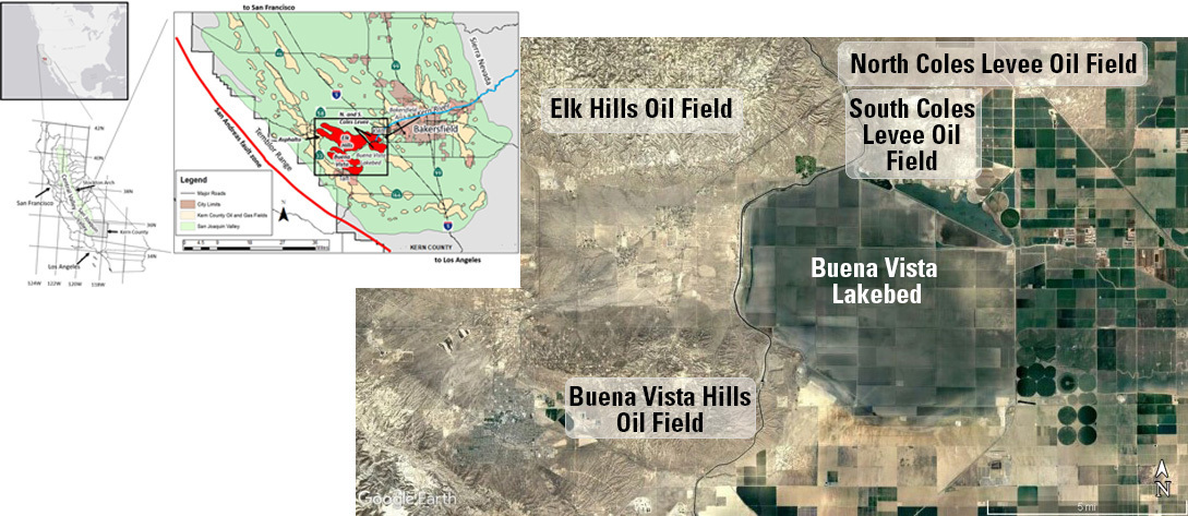
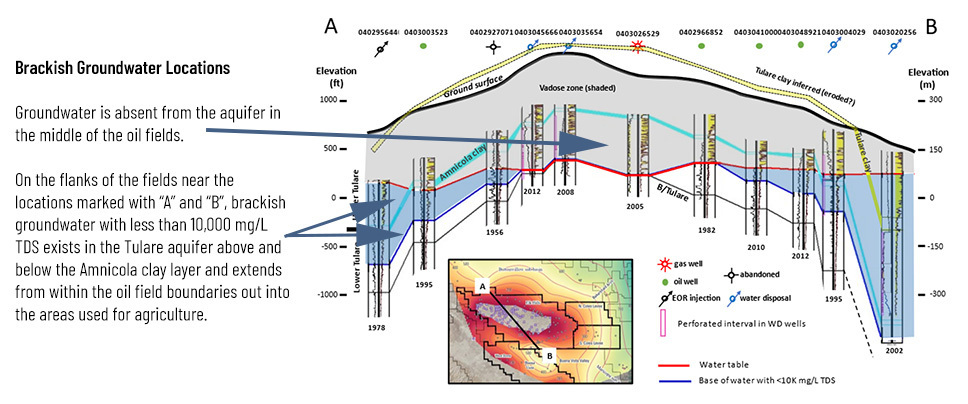
The Tulare aquifer contains useable groundwater and extends across the area
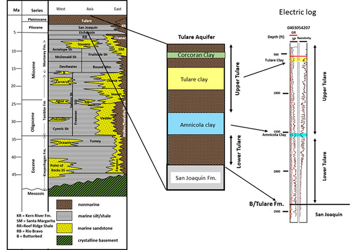
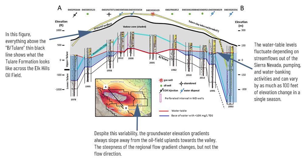
There are clay layers within the Tulare Formation that are displayed in the stratigraphy graphic below. The Corcoran Clay Member of the Tulare Formation occurs as lenses with patches of unconsolidated sands between, and the Tulare clay is present in synclines. The Amnicola is the bottom clay layer and does form a consistent barrier separating the Upper and Lower Tulare aquifer.
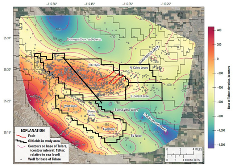
This figure shows where the bottom of the Tulare Formation is with respect to sea level. Although not depicted by this two-dimensional map, the Tulare aquifer is thinner on the ridge tops and gets much thicker as you move into the valley.
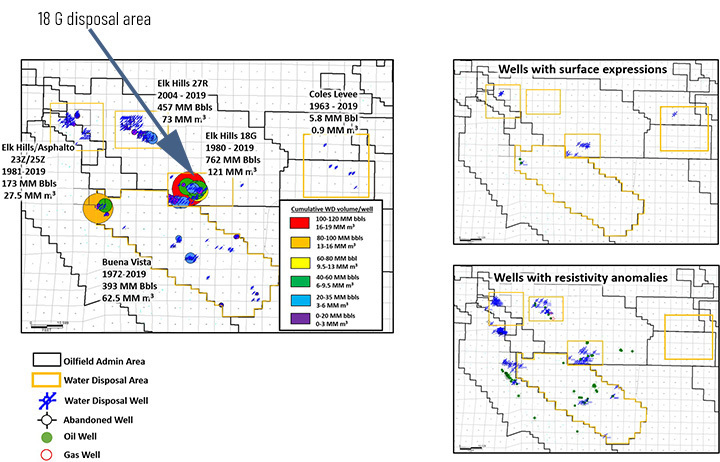
Effects of produced water disposal by underground injection on groundwater quality and associated surface expressions
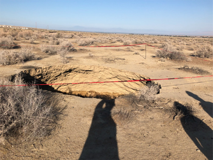
Two different types of changes caused by injection of produced water were noted in this study—salinity increases and surface expressions. Surface expressions are caused by pressure build ups around injection wells that create enough force to shift ground at the land surface. The volume of fluid injected is directly related to the risk of these changes occurring—more net fluid injection creates more risk. This picture shows a surface expression in the Elk Hills Oil Field.
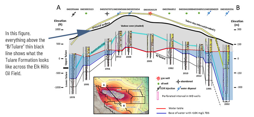
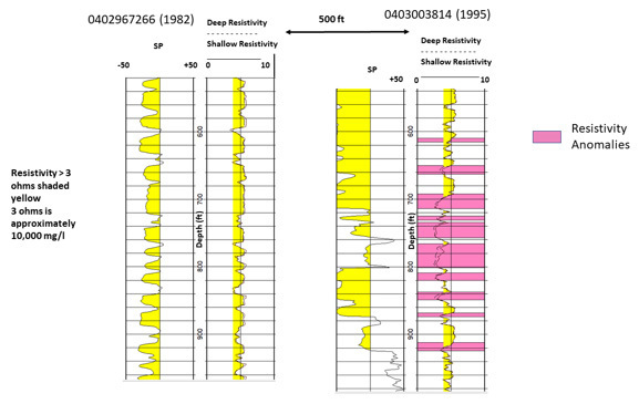
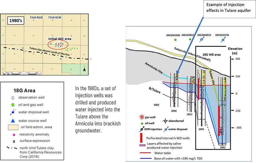
Resistivity anomalies are those well pairs where more recent resistivity and porosity data show salinity changes adjacent to injection wells. An example of how these changes are identified using well-record data is presented in this figure. The pink shading shows where salinity changed between 1982 and 1995.
Changing management approaches in the 18G disposal area of Elk Hills Oil Field
Produced water disposal practices have evolved in the 18G area along the southern boundary of the Elk Hills Oil Field.
The main conclusions are:
- Tulare Formation is only formation with groundwater salinity (TDS) < 10,000 mg/L
- Some newer well logs show areas of abnormally low resistivity indicating that past disposal injection activities have caused increased salinity in sands containing water with less than 10,000 mg/L TDS. In some disposal injection areas, surface expressions have occurred—especially in southern Elk Hills Oil Field
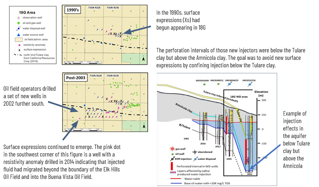
- Evidence from the 18G disposal injection area indicates that migration of injected produced water occurs in a down structure (downdip) direction in the direction of the slope of the water table
- Current disposal injection activities are focused on unsaturated intervals in the Tulare Formation that are below the Amnicola clay to provide added confinement, prevent over-pressuring, and avoid waters with less than 10,000 mg/L TDS